
*** Update 1/3/13 – I realized that since I complied the GUI in 64-bit MATLAB it would only run on other 64-bit computers, I have since added a 32-bit version of the PKG file to my SkyDrive folder. I also got rid of the running code at the bottom, it was redundant and was not displaying correctly, please see my SkyDrive folder for the .m files.***
Background
I wrote this custom MATLAB GUI using MATLAB GUIDE in MATLAB 2013a and then compiled it as a standalone executable application. I designed this software around our teams braking goal of having any driver reliably lock the brakes at competition; i.e. minimizing the force to lock each tire. I’m sure there may be more efficient ways of optimizing the code and there may be errors within the code, so feel free to openly modify and share this code for noncommercial use.
Downloading
The associated files can be downloaded via my SkyDrive folder located at: https://skydrive.live.com/redir?resid=9CB2544B3B29F089!33634&authkey=!AA9y65Li3s22itA&ithint=folder%2c.fig
To run the standalone application you must have 2013a MATLAB Compiler Runtime (MCR 8.1) installed on your computer. This can be downloaded at http://www.mathworks.com/products/compiler/mcr/ (for PC, Linux, and MAC). Then please download and run the “Braking_Software_12_30_13_pkg” file from my SkyDrive, either in the 32-bit or 64-bit version. This file is less than a megabyte.
If you feel comfortable with MATLAB and have it installed, you could also download the .m and .fig files and freely edit the code.
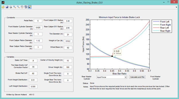
Using the Software
I defaulted the variables and constants to the assumed values of our 2013 car. I also included an adapted tire friction curve from tire data embedded in the code with the ability to apply a linear correction factor to match any testing data. Every graph is graphed with respect to bias bar percentage adjustment (really the only easily adjustable part of our system). Each tire is then graphed at the point where wheel lock occurs.
The beauty of this software is that it iterates to solve which tires lock first, then flags those tires to change the equations from using static friction to dynamic friction. Thus the vehicle dynamics can radically change once a single tire is locked, changing the weight transfer and thus making it either easier or harder to lock those last tires. Then it essentially tells you the sweet spot to adjust the bias bar to minimize driver input force.
For example, a driver weighing 160 lbs. in a car with no aero kit biased 40% (biased slightly to the rear tires) would need to apply a little over 100 lbs. of force on the brake pedal to first lock the rear right then the rear left tire. Then the same driver would need to apply about 120 lbs. to lock the front tires. See the figure below as reference.
Note: other graphs can look much more confusing, so don’t become overwhelmed. I found these graphs useful only for their maximum values to import into an FEA study on different brake components.
**update: the above screenshot contains an error. The static COF is actually built into the software based on a derived polynomial for tire data and weight. So the “Static CoF Tires” should be “Kinetic CoF Tires” and the “Kinetic CoF Correction Factor” should be “Static CoF Correction Factor” to manipulate the tire data to match real life conditions

Leave a comment